The local triggering system uses different cables to send gates to the ADCs than the `DAQ trigger'. These are labeled G0,G1,G2,and G3, corresponding to each of the ADC crates. These cables come from rack 2, crate 1, slot 12. Simply unplug the normal gates and plug in the local cables. The BOS and EOS gates to the LGD need to be disabled as well (the gates are unplugged, but the laser will still fire on EOS). See `Configuring the LGD' for details on how to do this. In addtion, the `Level 1 Clear' cable should be unplugged from the patch panel in rack 2, and the `QDC Busy' cable should be unplgged from the MAM. DAQ will need to be re-intialized with a configuration file that does not read out the LGD. In addition, the `MAM bypass' switch in the control room needs to be set, since the MAM normally provides the level 2 trigger strobe.
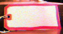
The cables that need to be moved are labeled with tags. The tags with the red outline are cables that are only for the DAQ trigger :

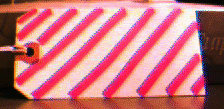
The cables with the red hash marks are for local triggering only :

The local triggering system provides a means of gating the LGD, firing the laser, and firing the ADCs' internal test pulser without any involvement from the DAQ system. As can be seen from the logic diagram. An IUCRF is used to control the triggering. The local triggering system is used by gDAQ and testLGD. The hut must be in `local' mode for these programs to work.
Several tools are available for verifiying that the local triggering is hooked up properly.
The 4 crates of IU ADCs draw more power than a standard FASTBUS power supply can handle, and are equiped with special high current supplies. There is one spare power supply, which should not be used anywhere other than to replace a bad ADC power supply. The supplies run off of 208V single phase power. The power goes through a special interlock box before it gets to the supply. The interlock box gets it's `operating' power from the same outlet strip that powers the fanns for the crates. The fans and the interlock boxes should allways be plugged into these strips. This assures that the crates cannot be turned on without the fans being on. There is a button on the interlock boxes. Pushing this enables the power to the supplies.
Crate 0 should allways be the on if the other crates are. This is because of how the cooling system is instumented (see below). The +5V, -5.2V, and -2V supplies run through standard FASTBUS supply cables to the backs of the crates. The +15V and -15V supplies are handled differently, because of the abnormally high current draw on these supples.
The FASTBUS backplane is split into two halves for power distibution. Normally, these halves are tied together and fed from one power lead on each voltage. Unfortunately, the +15V and -15V contacts are only rated for 25A, and at turn on, the crates draw 50+ Amps, and under normal operating conditions, they draw ~30A at these voltages. Thus we use the split backplane on these crates. The +/-15V leads from the supply go through a fuse box located next to the interlock boxes. These boxes split each voltage onto two leads which each run through 25A fuses before runnning to the crates, one lead to each half of the backplane. The return for these supplies comes from the large return bus on the back of the crates.
Typical current draws for the supplies are listed in the hut, and below:
Due to the high power drawn by the crates (~2 KW under normal operating conditions), a special cooling system is needed for them. There is a FASTBUS fan unit located above and below each crate. In addition, a 5 ton air conditioning unit is ducted into the crates. The thermostat for this unit is located above crate 0 (This is why crate 0 should allways be on). This thermostat should not be adjusted (neither should the others in the hut).
As an additional safeguard, there is a temperature interlock located above each crate. These are set at about 100 F. If the output temperature of the crate gets to high, the interlock trips, and the power to the relevent supply is cut off at the interlock box. The power should not be re-enabled without determining the cause of the trip (The only trips we have had were due to crate 0 being off, and thus the AC unit was not running).
** 1/11/95 R.L.