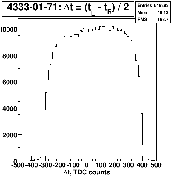
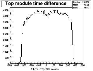
1) Splitters vs linear fan-in/fan-outs
After a lot of testing and head-scratching, the dip in the middle of a time-difference distribution was traced to linear fan-in/fan-outs. Apparently, these modules don't like when large signals appear at their inputs almost simultaneously. Replacing fan-outs with splitters eliminated the dip in the center.| with splitters | with linear fan-in/fan-outs |
 |
 |
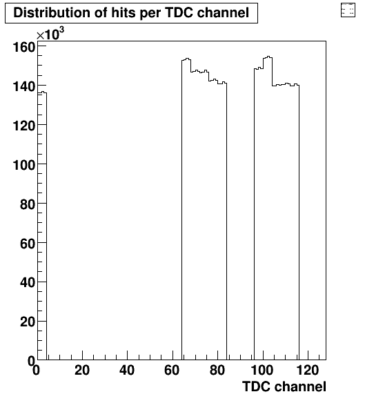
2) Changing TDC calibration
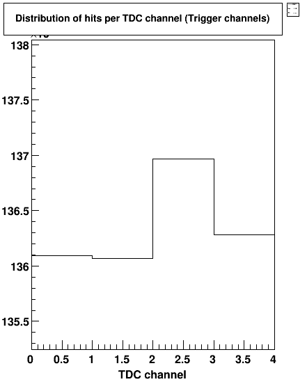
VX1290A TDC has 100ps clock. The bin size of 25ps is achieved by sending 4 copies of the signal through 4 RC-delay circuits into 4 TDC channels. RC-delays are calibrated in free-running TDC mode to be exactly 25ps, 50ps, 75ps and 100ps. However, after switching to triggered mode, a mis-calibration is observed (right plot) on the level of about 1%. The reason for that is not clear but this will have some impact on timing resolution.| Left - trigger, middle - 5 left PMTs, right - 5 right PMTs |
Zoom of the trigger hits |
 |
 |
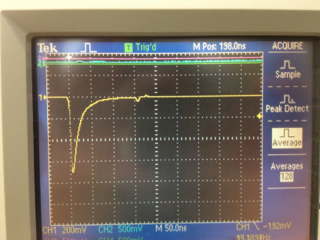
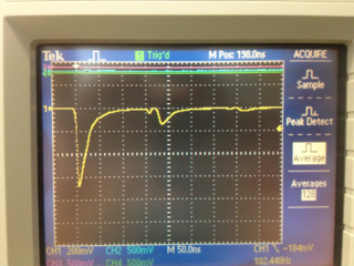
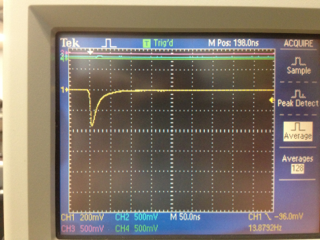
3) Reflection from splitters
Even with balanced 50-50 splitters, we see reflections at about 7% level of the initial signal. The left plot above (taken at 90mV threshold) gives an idea about the percentage of events where reflections exceed 90mV (@1.50kV HV) - compare left trigger group with middle and right PMT groups. Reflections happen exactly at twice the cable length (~160ns for 50' cable). These reflections originate from the splitters (left plot below), and not from the scope (middle plot), ADC or LED. Puting 50 Ohm terminator at PMTs eliminates these reflections (right plot) by sacrifying half of the signal. One possible reason for reflections: 16.5 Ohm resistors are used in the splitters instead of 16.7 Ohm.| No terminator at PMT | No terminators at PMT & scope | With terminator at PMT |
 |
 |
 |
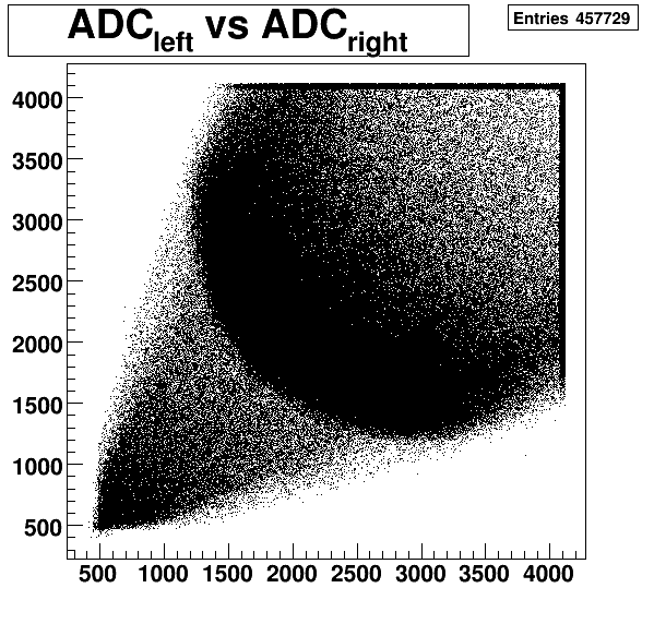
4) HV balancing
We are discussing if we need to do HV adjustment ("gain-balancing") while testing completed modules with cosmic rays, or do all tests at the same HV (like 1.5kV). The idea is to have minimum-ionization peak somewhere in the middle of the ADC range as shown on the plot below. For adjustment, three possible approaches can be used:a) Adjust them manually by looking at the scope;
b) Pre-calculate expected HV based on the measured tube's gain at 1.75kV and assuming the same gain dependence on HV for all tubes;
c) Do iterative HV adjustments by collecting some statistics, fitting it, adjusting HV, collecting statistics again, and so on. This is the approach which will be used with TOF in the hall, but it may be too slow with cosmics.
 |